Not Gate Circuit Diagram Using Diode
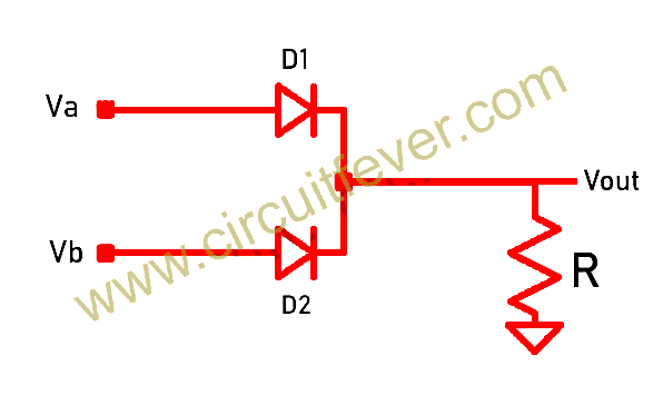
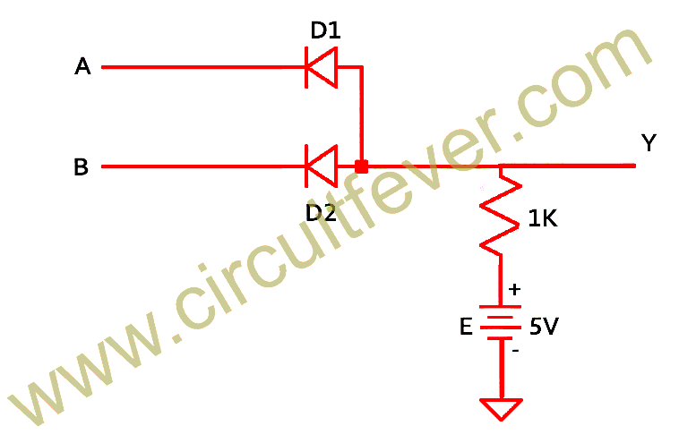
Logic gates using diodes and transistors Using diodes gates logic gate circuit transistors inputs output fever Working of or gate using diode
AND Gate: What is it? (Working Principle & Circuit Diagram) | Electrical4U
Logic gates using diodes and transistors Gate nor using transistor diode breadboard circuit logic dtl gates diodes implementation construction Logic signals
Diode logic gates stack electrical exchange engineering gate circuit pdf questions answered oct
Circuit analysisNor gate using diode and transistor (dtl) Digital electronics-logic gates basics,tutorial,circuit symbols,truthExplain logic and gate and its operation with truth table.
Diode logic circuit diodes gate input 12v circuits led two control using 5v voltage do sparkfun schematic coupled calculations emitterGate logic ic without eleccircuit diode circuit learn simple resistors Designing and gate using diodesGate diodes input output.

Gate circuit diode diagram diodes electrical4u 5v apply principle working above first
Gate diode input logic gates circuit transistor digital truth electronics their symbols circuitstodayAnd gate: what is it? (working principle & circuit diagram) Learn simple and and or logic gate without icUsing diodes logic gates gate circuit transistor transistors.
Learn simple and and or logic gate without icGate diodes using logic truth table operation input explain its fig ☑ diode logic circuits examplesGate diodes logic use simple ic without diode eleccircuit using learn resistors.

Scavenger's blog: or gate
Gate diode diodes transistors scavenger using logic gates circuitDiode logic gates lab operation resistor current ☑ diode not gate circuit.
.


Scavenger's Blog: OR Gate

diodes - Logic gate on negative signals - Electrical Engineering Stack

Logic Gates Using Diodes and Transistors - Circuit Fever

Learn simple AND and OR logic gate without IC | ElecCircuit.com

AND Gate: What is it? (Working Principle & Circuit Diagram) | Electrical4U

NOR Gate using Diode and Transistor (DTL)

circuit analysis - Diode Logic Gates - Electrical Engineering Stack

Learn simple AND and OR logic gate without IC | ElecCircuit.com

Working of OR Gate Using Diode