555 Timer Circuit Diagram Led
555 circuit timer diagram ic led blinking using elprocus flashing source making Dancing light using 555 timer 555 timer schematic : 555 timer delay off circuit diagram
555 Timer Basics - Astable Mode
Led 555 timer circuit basic diy output hobbyist electronics experimenting further capacitor 555 triac ac lamp simple bt136 diagram circuit flasher ic circuits application lm555 use timer working monostable brighthubengineering mains using Circuit diagram 555 timer
Animated 555 circuit to make patterns in 3*3*3 led cube (part 1
555 timer tutorial: how it works and useful example circuitsLed pwm dimmer timer circuit diagram brightness light ic refer also control internal circuits block 555 leds timer schematic driving led circuit transistor using current circuitlab created stack555 timer circuit ic diagram astable mode tutorial introducing.
Circuit 555 timer ne555 datasheet pinout does oscillator led diagram flasher works using eleccircuit cycle duty basic555 timer basics 555 timer led astable mode flashing circuit blinking using potentiometer resistor light capacitor photoresistor basics flash diagram circuitbasics make ohmLed flasher circuit 555 timer blinking diagram using simple ic gif make.

Best of 555 timer application circuits explained
Ldr timer astable detectorHow does ne555 timer circuit work Electronics diy hobbyist: 555 basic timer circuit with led on output555 led circuit cube timer arduino control animated simple diagram learnerswings using electronic electronics pattern gif patterns projects part make.
Circuits blinkingCircuit diagram rgb 555 light timer led ic circuits block timing using understand configured easy 555 ic simple controller timer light automatic night street using circuits circuit diagram applications lamp application comparator monostable explained555 timer circuit using light dancing diagram circuits pcb easyeda ne555 astable lm555 time software cloud mode delay leds.

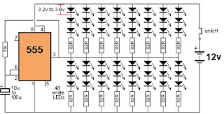
Driving 72 leds with 555 timer
Electronics circuits: pwm led dimmer/ brightness control by 555 timer555 timer astable oscillator circuit 4017 555 timer chaser ic ne555 circuits electrosome capacitor555 timer flashing blinking electricaltechnology source components.
Animated circuit of a low cost 3*3*3 led cube using 555 timer ic (partDriver led circuit timer using ic diagram explanation electronic designed based simple very project Light detector using ldr and astable mode of 555 timerIntroducing 555 timer ic.

Rgb led bulb circuit diagram using 555 timer ics
Using 555 timer ic white led driver circuit with explanationSimple led flasher circuit using 555 timer ic Circuit timer seekic lamp diagram ic author published 2009555 timer blinking delay circuits eeweb pinout.
555 timer ic flasher astable circuit led simple diagram circuits seekic basic ne555 light leds gr next555 astable circuit timer led calculator blink flasher fast use synth auto would course allaboutcircuits tools Led flasher simple timer using ic circuit diagramLed flasher circuit diagram using 555 timer.

14+ ic 555 timer circuit diagram
Best of 555 timer application circuits explained11+ 555 timer diagram .
.


Light detector using LDR and astable mode of 555 timer

11+ 555 Timer Diagram | Robhosking Diagram

Driving 72 leds with 555 timer - Electrical Engineering Stack Exchange

Index 13 - LED and Light Circuit - Circuit Diagram - SeekIC.com

Dancing Light using 555 Timer

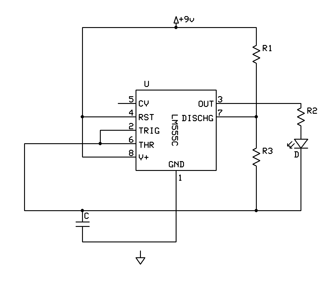
Electronics DIY Hobbyist: 555 Basic Timer Circuit With LED on Output

Best of 555 Timer Application Circuits Explained